
Fluid power has become a vital component in our ability to perform work: it harvests our crops, takes our waste to the landfill, moves the landing gear, entertains and protects us, and all with a power density and flexibility that is unmatched in any other power transfer system. However, when it comes to efficiency, fluid power systems are not very high on the list. This article series will ask us to think differently about our fluid power systems. We will look at energy in a different way and discover ways to transform fluid power energy to make our systems more efficient, and then be able to make better use of the new and improved components available to us.
It happened around 1982. A customer had an old bulldozer. He had bought a newer backhoe attachment but would not be operating both at the same time. He wanted to run both from the same hydraulic system. The problem was that the dozer system ran with 20 gpm at 1500 psi, while the newer backhoe required 10 gpm at 3000 psi. The solution was a selector valve that would divert the flow from the dozer into a two-section displacement flow divider with equal displacement for each section. One of the outlet ports from the divider was directed to the tank and the other to the new backhoe. The result was 10 gpm available to the new equipment at a pressure of 3000 psi.
I mention this incident because understanding this simple flow divider is going to be the key in grasping how we are going to transform fluid power. It isn’t magic. It’s simple math.
For those of you who are unfamiliar with the old technology of this type of flow divider, let me give a brief explanation. The device is made up of two or more separate fixed-displacement motor/pumps that are mechanically connected. The most common configuration of this type of flow divider is with gear motor/pump sets. This is why it is often referred to as a “gear flow divider.” The fact is, any combination of positive-displacement motor/pumps could be used. In our discussion, we will refer to them as pressure/flow transformers or simply, transformers. The most common use for them is to synchronize actuators. The flow is divided in one direction and combined in the opposite direction. It can synchronize a group of actuators in both directions.
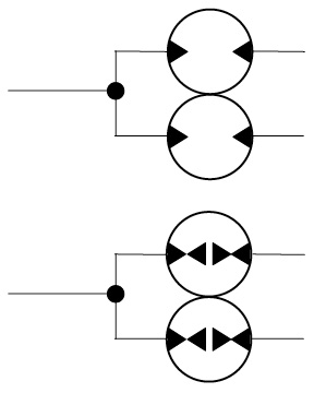 The most common symbol for the displacement divider is a group of fluid motors (in this case, two) that are touching as in the image on the left.
Because the device both drives and is driven by the fluid, a better symbol is shown at left. This is the symbol we will use in our discussion.
When flow enters the unit at one side, it is divided proportionally based on the displacements of the sections. What makes this different from a spool-type flow divider is the fact that the power is not restricted but merely divided proportionally. The sum of the power exiting will equal that of the power entering. For example, with a two-section device, if 20 lpm at 10 MPa exits from one port and 20 lpm at 0 MPa exits from the other port, a total of 40 lpm will have to enter at port 1 at a pressure of…? You got it. The input pressure would be 5 MPa. Power in equals power out.
(20 lpm x 10 MPa) + (20 lpm x 0 MPa) = 200 units of power
The input will also have to equal 200 units of power.
40 lpm x 5 MPa = 200 units of power
The pressure/flow transformer has been around for a long time. It is not compact and cannot easily be contained in a manifold. It is not adjustable. A typical 50/50 unit will divide the flow in half ±5%, depending on the pressure difference between the outputs. When compact restrictive flow dividers were developed, the displacement divider was relegated to applications where size and accuracy were not a priority. Very little attention was paid to the energy advantages that could be gained by its use.
Let’s take a look at several applications of the pressure/flow transformer, some of which are often overlooked. We will limit our descriptions to devices with only two sections. The following examples are not intended to be fully operational circuits but are ways to configure the transformers.
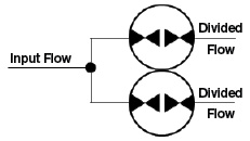 1. Flow Divider
In this case, the flow entering at the inlet is simply divided into portions equal to the displacements of the sections. If each section has a displacement of 10 cc, a 20 lpm input would result in 10 lpm from each outlet. If one section has a displacement of 10 cc and the other a displacement of 20 cc, the same 20-lpm would be divided so that 6.67 lpm is delivered from the first section and 13.3 lpm from the larger section. The flow is divided in proportion to the displacements of the sections.
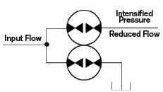 2. Pressure Intensifier
Here we begin to see how this device affects pressure as well as flow. The pressure at the inlet acts on the combined displacements of the sections. The shaft that connects the sections develops a torque based on the pressure and combined displacements. When some portion of the outlets (in this case, just one) is directed to the reservoir, all of its force is conveyed through the connecting shaft to the remaining section(s). An input pressure of 10 MPa would result in an outlet pressure of near zero MPa from the section(s) directed to the reservoir, and 20 MPa at the outlet directed to the work. The pressure intensification occurs independent of flow. If the unit is stalled, the pressure will remain. This is the arrangement that was used for the dozer/backhoe.
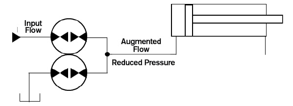
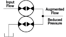 3. Flow Augmentation
This function uses the flow-combining characteristic of the transformer. One section is used as a motor and the other as a pump. The motor section drives the pump section by means of the connecting shaft. The pump outlet and the motor outlets are combined. But remember, power out has to equal power in: 20 lpm entering the motor portion at 20 MPa will cause the pumping portion to draw 20 lpm from the reservoir for a total output of 40 lpm at 10 MPa. 20 lpm x 20 MPa = 40 lpm x 10 MPa.
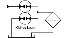 4. Kidney Loop
A small amount of energy from the hydraulic system can be used to drive a pressure/flow transformer for a low-pressure kidney loop. This can reduce installed cost by eliminating an extra electric motor with its controls.
5. Two-Pressure/Two-Speed Clamp Circuit
This is using the pressure intensification function with the addition of a pilot-operated directional valve. The cylinder will extend at full speed until the pressure reaches the pilot requirement. The cylinder will continue to extend, but at half the speed and up to twice the pressure. When the cylinder stops, the flow also stops but the high pressure remains.
6. Two-Pressure/Two-Speed Motor Circuit
This is similar to the clamping circuit, but using a motor instead of a cylinder. As pressure builds in the line (torque requirements increase), the directional valve shifts to reduce flow and intensify pressure. This could also be used as a multi-speed transmission with as many speed ratios as there are sections.
 7. Regeneration Two-Speed Cylinder Circuit
The pressure/flow transformer is placed at the outlet of the cylinder. A portion of the return flow is added to the cylinder inlet, increasing the speed but reducing the force. The inlet to the pressure/flow transformer would have half the pressure of the inlet to the cylinder. This produces the resistive load that reduces the cylinder force and drives the divider to send half the flow to the blind end of the cylinder. When the resistive load on the cylinder reaches the pressure that shifts the directional valve, all flow from the cylinder is directed to the reservoir. The cylinder slows down and full force is available.
 8. Regeneration Two-Speed Motor Circuit
The pressure/flow transformer is placed at the outlet of the motor. Half of the return flow is added to the motor inlet, increasing the speed but reducing the torque. Using the 50/50 divider, the inlet to the divider would have half the pressure of the inlet to the motor. This produces a resistive load that reduces the motor torque. When the pressure to the motor reaches the point where the directional valve shifts, all flow from the motor is directed to the reservoir. The motor slows down and full torque is available.
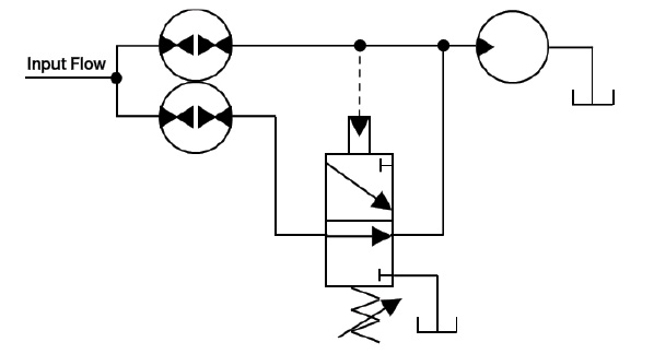
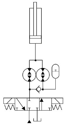
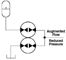 9. Accumulator Stored Energy Augmenter
In an application where accumulators are used for energy storage, this arrangement can reduce the size of the storage volume. With a pressure/flow transformer driven by the accumulator energy, half of the flow is drawn from the reservoir and half from the accumulator, doubling the storage capacity. The outlet pressure is half the accumulator pressure, reducing the pressure drop across any control orifice.
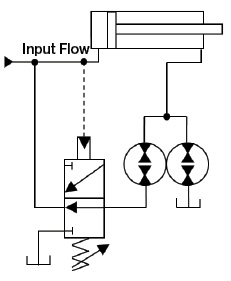
10. Pressure Reducing
The pressure/flow transformer can also be used as a pressure-reducing circuit, replacing a pressure-reducing valve. The pressure available to the cylinder will be reduced in proportion to the ratios within the transformer. Different ratios can be used depending on the desired pressure.
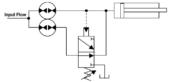
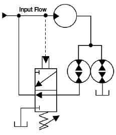
 11. Energy Recovery
The pressure/flow transformer can also be used to recover energy, such as when a load is lowered or when a load is decelerated. In the figure, energizing the solenoid to lift the cylinder directs flow to the displacement divider and through the check valve to the accumulator. Fluid fills the accumulator until the pressure reaches the cylinder load resistance. The fluid is then combined through the transformer and lifts the cylinder. When the solenoid is energized to lower the cylinder, the cylinder becomes the energy source and flow drives the transformer as a pressure intensifier; half the flow is directed to the reservoir and half to the accumulator. When the cylinder is fully retracted, the pressure in the accumulator is nearly that required to lift the load. The next time the solenoid to lift the cylinder is energized, the transformer becomes a flow augmenter with half of the flow and most of the energy coming from the accumulator. Only half the flow from the source will be required to lift the cylinder at full speed. About 75% of the energy is recovered in the accumulator.